
Implementing VLSM, FLSM, and CIDR Best Practices
Utilization of IP addressing is an important role of a network engineer. Therefore, they must ensure the availability of IP addresses to allocate to their clients. Furthermore, there are some techniques through which he will be able to its availability. Specifically, they must know VLSM, FLSM, and CIDR notation, through which they will ensure the availability of IP addresses. VLSM is an important part of the Cisco CCNA exam. It stands for “Variable length subnet mask”. It means a subnet mask that can vary in different lengths. The purpose of it is to decrease the wastage of IP addresses. Before the introduction of VLSM, network administrators used FLSM, which stands for the full-length subnet mask. Similarly, CIDR is also used in conjunction with VLSM, which denotes network bits with IP address in slash notation. Anyhow, Will use the following diagram to play with FLSM, VLSM, and CIDR.

Full Length Subnet Mask (FLSM)
There is a need for different hosts at every network segment. Consequently, if we have an IP address 192.168.10.0/24, to assign these hosts, we will divide this network according to the need. As the maximum number of hosts required is 28 hosts, and we have learned in subnetting that if the block size is lower than 32, then we will assign /27 networks to that segment. Therefore, our sub-netted network will be 192.168.10.0/27. In this way, every segment In the diagram will get 30 hosts, whether they require it or not. However, on the other hand, it is a waste of IP addresses because some segments require 2 and 5 hosts per network, but we are assigning 32 blocks. This is what we call the assignment of IP addresses to the host Full-Length Subnet Mask (FLSM).
Variable Length Subnet Mask (VLSM)
Every segment is getting a fixed number of hosts. However, this is not the best practice to waste our IP addresses. Specifically, we are wasting 10, 16, 28, 25, and 2 hosts in segments 1,2,3,4 and 5 respectively. To stop the wastage of IP addresses, we need a mechanism that reduces the wastage of IP addresses, and that mechanism is a VLSM (variable length subnet mask). From the name, it clearly defines that there will be different subnet masks for each network. With VLSM enabled, vendors can effectively stop the wastage of IP addresses. The next step to avoid wasting IP addresses was VLSM. In this way, VLSM ensures, that there will be different subnet masks for each network. To illustrate this, we will get help again from the previous diagram.
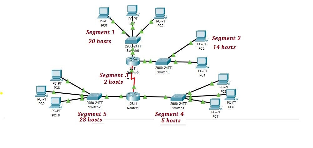
VLSM, on the other hand, will not assign an equal subnet mask to every segment; but it assigns it according to their need. For example, suppose a network address for the above diagram is 192.168.10.0/24. As the maximum number of hosts required in a diagram is 28 hosts, it will assign /27 subnet mask to segment 5 because it contains 28 hosts. similarly, it will also assign an /27 subnet mask to segment 1 because it is greater than 16 and less than 32 blocks, we can’t assign 16 blocks to the segment but we will also assign /27 subnet mask to segment 1. Remember, you should allocate IP addresses in VLSM, first to the larger blocks and then to the smaller ones.
Implementation of VLSM
As segment 1 and segment 2 contain the highest number of hosts, we assigned them first. Simply larger network segment will come first in a calculation. In our case segment 5 will come first, then segments 1, 2, 4, and 3 respectively.
In the above topology, there are 4 networks, of which four networks are LAN and one is WAN. The network we have is 192.168.10.0/24, and the default mask of it is 24. Now, if we subnet this IP, then we have to divide this IP into chunks of 30, or a block size of 30 because there is a need for a maximum of 30 hosts per block as we implement VLSM, FLSM, and CIDR.
192.168.10.0/27
192.168.10.32/27
192.168.10.64/27
192.168.10.96/27
192.168.10.128/27
192.168.10.160/27
192.168.10.192/27
192.168.10.224/27
Now, if we apply the above subnets to networks, we have decreased the wastage of IP addresses. Previously, with a /24 prefix, there was a significant wastage of IP addresses. Some networks require only 2 hosts or 5 hosts. Additionally, some networks require only 2 or 5 hosts. Furthermore, If we apply the /27 with 32 blocks, there is still a waste of IP addresses. However, by the use of VLSM FLSM, and CIDR we will decrease more wastage of IP addresses.
In such a situation, we use VLSM. The formula used for VLSM is as follows:
No of subnets = 2n-2
Where n = number of bits borrowed
Additionally, Block size = total no. of addresses
So, Block size = 256 – Mask
1st represents networks while zeros represent host. The table used for the decimal equivalent of a bit
Bits Representation for VLSM
128 64 32 16 8 4 2 1
0 0 0 0 0 0 0 0 = 0
1 0 0 0 0 0 0 0 = 128
1 1 0 0 0 0 0 0 = 192
1 1 1 0 0 0 0 0 = 224
1 1 1 1 0 0 0 0 = 240
1 1 1 1 1 0 0 0 = 248
1 1 1 1 1 1 0 0 = 252
1 1 1 1 1 1 1 0 = 254
1 1 1 1 1 1 1 1 = 255
Segmentation of Networks in VLSM
| 1) Segment 5 Required hosts = 28 Network= 192.168.10.0/27 Host Range= 192.168.10.1 – 192.168.10.30 Broadcast IP= 192.168.10.31 Allocated hosts= 30 Only 2 IP address is wasted | 4) Segment 4 Required hosts = 5 Network= 192.168.10.80/29 Host Range= 192.168.10.81 – 192.168.10.86 Broadcast IP= 192.168.10.87 Allocated hosts= 6 Only 1 IP address is wasted |
| 2) Segment 1 Required hosts = 20 Allocated hosts= 30 Network= 192.168.10.32/27 Host Range= 192.168.10.33 – 192.168.10.62 Broadcast IP= 192.168.10.63 Only 10 IP address is wasted | 5) Segment 3 Required hosts = 2 Network= 192.168.10.88/30 Host Range= 192.168.10.89 – 192.168.10.90 Broadcast IP= 192.168.10.91 Allocated hosts= 2 No IP address is wasted |
| 3) Segment 2 Required hosts = 14 Allocated hosts= 14 Network= 192.168.10.64/28 Host Range= 192.168.10.65 – 192.168.10.78 Broadcast IP= 192.168.10.79 No IP address is wasted |
We are taking another example as shown below
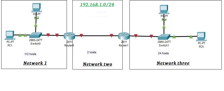
Network 1 requires 112 hosts, Network 2 requires 2 hosts, and Network 3 requires 24 hosts In this scenario, as the largest block size is 112 hosts, if we are using FLSM, then there will be only two networks with a 128-block size. Consequently, there will be no IP address block available for the 3rd network.
Introduction to CIDR
CIDR stands for classless inter-domain routing, and It plays an important role in subnetting, a method that allocates IP addresses. Notably, It was introduced by IETF in 1993. Before the introduction of CIDR, the classful IP address was prevalent. However, with the transition from classful to classes IP addressing, the need for CIDR became apparent. For instance, when observing an IP address like 10.10.10.10 and looking at its 1st octet, it’s clear that it’s a class A address. We know that it is a class A address due to its 1st octet range 0-126 and also its subnet mask /8. So, we have gotten the idea that it’s a class-A address. Similarly, the concept for classes B, C, D, E, and F follow a similar pattern.
Roll of CIDR
When the classless IP address was introduced, a method was required to represent it and that’s where VLSM, FLSM, and CIDR came into play. Notably, the subnet mask is used to represent how many bits are designated for the network ID and how many bits are for the host ID. In CIDR notation, network masks are represented differently, as seen in examples like 10.10.10.10/8, which is also referred to as slash notation. Moreover, a CIDR was introduced, and the number of network bits and the number of host bits were determined. Notably, Internet Service Providers (ISPs) utilize CIDR to allocate IP addresses to their clients.
Suppose we have a classless IP address with CIDR or slash notation; for example, 10.10.10.10/12.
/12 means that 12 bits are on (1) which represents a mask or it represents a network of bits.
Some important CIDR values
| Subnet Mask | CIDR |
| 255.0.0.0 | 8 |
| 255.128.0.0 | 9 |
| 255.192.0.0 | 10 |
| 255.224.0.0 | 11 |
| 255.240.0.0 | 12 |
| 255.248.0.0 | 13 |
| 255.252.0.0 | 14 |
| 255.254.0.0 | 15 |
| 255.255.0.0 | 16 |
| 255.255.128.0 | 17 |
| 255.255.192.0 | 18 |
| 255.255.224.0 | 19 |
| 255.255.240.0 | 20 |
| 255.255.248.0 | 21 |
| 255.255.252.0 | 22 |
| 255.255.254.0 | 23 |
| 255.255.255.0 | 24 |
| 255.255.255.128 | 25 |
| 255.255.255.192 | 26 |
| 255.255.255.224 | 27 |
| 255.255.255.240 | 28 |
| 255.255.255.248 | 29 |
| 255.255.255.252 | 30 |
| 255.255.255.254 | 31 |
| 255.255.255.255 | 32 |