
Rapid Spanning Tree Protocol: Reduce Downtime Like a Pro
Introduction
Rapid spanning tree protocol is the enhanced version of the legacy STP 802.1D which was designed primarily to improve the original STP. Its main objective is to prevent loops as well as reduce convergence time. Because, the IEEE 802.1D takes 30-50 seconds to fully functional, which is a great delay in modern digital networks. But, the RSTP takes a few milliseconds in case of link failure which makes it ideal for modern enterprise networks.
Port Roles in Rapid Spanning Tree Protocol RSTP
- Root Port: The best route to the root switch is known as the root port, or a port forwarding the traffic towards the root switch.
- Designated Port: A port connected to the other switch down the stream.
- Alternate Port: The switch marks the blocking port in RSTP as an alternate port.
- Backup Port: This is a port that provides an alternative path to the root switch but doesn’t forward traffic unless the primary path fails.
- Edge Port: Portfast-enabled ports are known as Edge ports in RSTP. But, if a switch is connected to the other side, then it will receive BPDUs and will lose its edge port status. Thus it will act as a normal STP port which will generate TCN.
Port States in RSTP
Instead of 5 ports in the legacy STP, it has only three states which are:
- Discarding: It is just like a blocking port that discards the incoming BPDU.
- Learning: This state will learn the BPDUs for 15 seconds.
- Forwarding: The active states which will forward the packets to the destination.
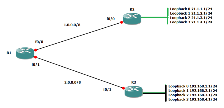
Lab Diagram for Rapid Spanning Tree Protocol RSTP
The following diagram will demonstrate RSTP with its configuration;

- Assign the name to the switches as switch1, switch2, and switch3
- Set its vtp mode server, and vtp domain as “marwat” on all the three switches
- Configure the trunk ports among all the switches
- Similarly, assign vlan 1 to the end devices such as computers
After the above configuration, run the rapid spanning tree protocol on all three switches as shown below in the screenshot;

Moreover, configure the portfast feature on the interfaces to which PCs like PC1, PC2, and PC3 are connected on all the switches.

Also, configure portfast for PC2 and PC3.
Now run the command “show spanning-tree” on one of the switches to check the result.

As highlighted, switch2 is running RSTP. Moreover, it marks the block port as an alternate port (Altn BLK).
After configuring Rapid STP, the switches will find alternative paths in milliseconds if any interface becomes shut down. It will not wait for listening, or learning, but the port will convert into forwarding immediately.
For more practice, shut down the interface Fa 0/1 of switch3 and at the same while, ping PC2 from PC3. Then you will find that there is no delay in the pinging.
What Will Happen If Another Switch is Connected to Switch3’s Fa 0/3?
As we have already written in the “Edge Port” definition, “Edge port” or portfast interface will convert into a normal STP port by listening to BPDUs. Just for practice, attach another Switch4 to the Switch3’s Fa 0/3. First, it will amber red, and after listening, to learning states, it will convert into a forwarding state. Let’s check it in the following screenshots.

After the listening and learning state, it will convert into the forwarding state as below;

If you want that no any other switch receive BPDUs on this port, then BPDUguard and BPDU filter can help in this regard. BPDUGuard and BPDU Filter blocks the BPDU on portfast interfaces. After configuring BPDUGuard and BPDU Filter, another switch will not be added to the topology.


Your article helped me a lot, is there any more related content? Thanks!