Switch Virtual Interface: The Ultimate Networking Hack
Introduction
It is essential to communicate devices in different VLANs for running operations smoothly. Switch virtual interface (SVI), making this with the help of the Layer 3 switch. Simply, SVI is the concept of intervlan routing through which we communicate different VLANs within the layer 3 switch. Thus, it eliminates the usage of external layer 3 devices such as routers.
What is Switch Virtual Interface (SVI)
The term virtual interface in SVI is an interface on a Layer 3 switch that acts as a gateway for a VLAN. It is a logical interface in a switch that allows VLAN’s traffic to be entered or left. VLANs will not communicate with each other without an SVI, because an SVI acts as a “doorway” or “gatekeeper.”
For example, if there are three VLANs on a Layer 3 switch,
- VLAN 10 for HR
- VLAN 20 for Sales
- VLAN 30 for IT
All three VLANs need their own SVIs to allow routing among them.
How Does Inter-Vlan Routing Work with SVI?
Routers are usually used for intra-network routing, but in today’s modern networks, Layer 3 switches are used for this task.
- SVI Creation: For each VLAN, we create a separate SVI by assigning them an IP address. This IP address acts as a gateway for the devices in each VLAN.
- Routing Configuration: After configuring SVI on the switch, the next step is to enable routing on the switch. This tells the switch that it can route traffic between VLANs based on the IP addresses assigned to each Switch Virtual Interface (SVI).
- Intervlan Routing: When a device in one VLAN wants to communicate with another VLAN, then it sends its traffic to the default gateway. The L3 switch checks its destination IP address, which then routes the packet to the appropriate SVI for that particular VLAN.
How to Configure Switch Virtual Interface Lab Topology
We will use the following lab topology for switch virtual interface. It consists of two networks, Network A, and Network B. In network A, we will configure SVI, while in network B, a router on a stick will be performed.

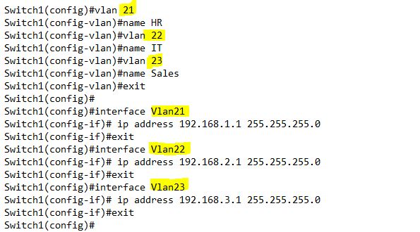
First, we are going to start from a beginner level. For this purpose, configure Switch1. Create three VLANs, and assign them IP addresses. Also, assign IP addresses to the computers in the VLANs as given in the screenshot.
Ping from VLAN21 to VLAN22, i.e., PC1 to PC3;

The reason is, that each VLAN has different network. For this, we must enable routing on the switch. We can only enable routing on the Layer 3 switch.

Now ping again;

This was simple, but now, how to communicate with the switch2 VLANs. It is not Layer 2 VLANs that were simple through VTP.
Create two VLANs, VLAN22 and VLAN23, on switch2, and assign them IP addresses. Connect the PC to each VLANs as shown in the screenshot. Create two virtual interfaces for VLAN22 and VLAN23 by assigning them an IP addresses. Similarly, assign Fast 0/3 and Fast 0/4 to the respective VLANs by making them access ports. At the last, enable routing on the switch.

Configure a trunk link between switch1 and switch2.

We configured SVI, trunk link, and enabled routing on both switches in network A. Now, ping from switch2 vlans to switch1 vlans.
Ping from PC5 to PC1. PC5 is connected with switch2, and PC1 is connected to switch1. Both are in different VLANs;

Similarly Ping from the same PC5 (VLAN22) again to VLAN22 and VLAN23. While below in the screenshot, ping to VLAN21 (192.168.1.1).

Although it ping, VLAN22 and VLAN23 virtual interfaces, but it was not successful to ping VLAN21 (192.168.1.1). Because, the switch2 routing table is completely converged. Check both the routing table;

Switch1 has three networks, while switch2 has two networks. Switch2 is missing 192.168.1.0/24 network. That is why it was not able to ping 192.168.1.1. For this, we will run a routing protocol like RIP version 2.

Again, check routing tables of both the switches;

How to Connect SVI with the Router?
We connected two switches having SVI, but now we want to connect these switches to the router. The purpose of our lab is to connect these VLANs with the network B.
Configure the Switch2 interface fast Ethernet 0/1 as trunk link, that is connected to the router.

Configure the router for different VLANs. For this purpose, create three sub-interfaces under fast Ethernet 0/1. 0.0.21 for Vlan 21, 0.0.22 for Vlan 22 and 0.0.23 for Vlan 23. Do not assign IP addresses on physical interfaces.

Ping all the VLANs from the router;

Configure Router on a Stick in Network B
To configure network B, there is one switch, on which we will configure two VLANs, VLAN 31 and 32. After configuring VLAN on switch3, we will connect them via router on a stick method. The switch3 is a layer 3 switch. Here VLAN 31 has named guests, while VLAN has named students.
Vlan 31 has an IP Network (172.16.0.0/16), while VLAN 32 has an IP address range (10.1.1.0/24). For more switch configuration, check the below screenshot:

In the above screenshot, after creation of VLANs, we have assigned interfaces to the respective VLANs. While at the last we configured a trunk link between switch3 and the router by allowing VLANs 31 and 32 on it.
For router configuration, see the below screenshot:

There are two sub-interfaces under fast Ethernet 0/1, which are fa 0/1.31 for VLAN31 and fa 0/1.32 for VLAN32.
Let us ping between the VLANs, e.g., from VLAN 31 to 32 and vice versa.

Now ping the other sides of the VLANs (VLAN21, VLAN22, VLAN23) from VLAN32.

PC10 from VLAN32 is pinging 192.168.3.10, but it does not ping 192.168.3.2. Because, 192.168.3.10 is configured on the router sub-interface, while 192.168.3.2 is the virtual interface at Switch3. That is why VLAN32 did not ping VLAN22 and VLAN23.
Similarly, it can also ping 192.168.2.10, but it will not ping any other interface IP. To resolve this issue, let us configure routing protocols like RIP on the router, and advertise all the IP addresses configured on the router.

Now ping VLAN21 and VLAN22 PCs from VLAN31’s PC9;

That’s is our a complete on SVI as well as on router on a stick. Explore our blog for more hands-on labs like these that will help you master practical CCNA skills and elevate your networking expertise to the next level!