What Is SNMP? How To Implement Different Versions Of SNMP?
.SNMP stands for simple network management protocol. It is an application layer protocol defined in the IETF RFC 1157. This protocol is used to monitor all the devices installed in a network. If you want to monitor all the devices in a network: what is configured in those devices, what is running in it, and how to manage all the network activities. Then, we can surveillance them from a central point through it. It uses UDP ports 161 and 162 for its communication. Port number 161 is used by the SNMP manager to send commands to the agents. Similarly, port number 162 is used by agents to send trap messages to the SNMP manager. The SNMP manager requests data from other devices, so it acts as a requester and when it gets that data, it starts recording that data.
Components of SNMP
The components of SNMP consist of the SNMP manager, SNMP manages devices with their agent software, and the database (MIB). It details are given below:
SNMP Manager
Typically, SNMP manager is software that obtains information and alerts. It uses UDP port 161 for its communication.
Agents
It is a process (software) running on a monitored device. The agent collects different types of information from network devices. It sends that information as a response to the request of the SNMP manager. It sends unsolicited messages (which is also called a trap) to the NM.
Management Information Base (MIB)
Network devices will gather different types of information about themselves and store that information in a local database. This database is called MIB. It is a hierarchical structure that represents a tree. MIB contains an object identifier (OID) which can help in identifying relevant SNMP information.
Managed nodes
These are the devices that are being monitored.
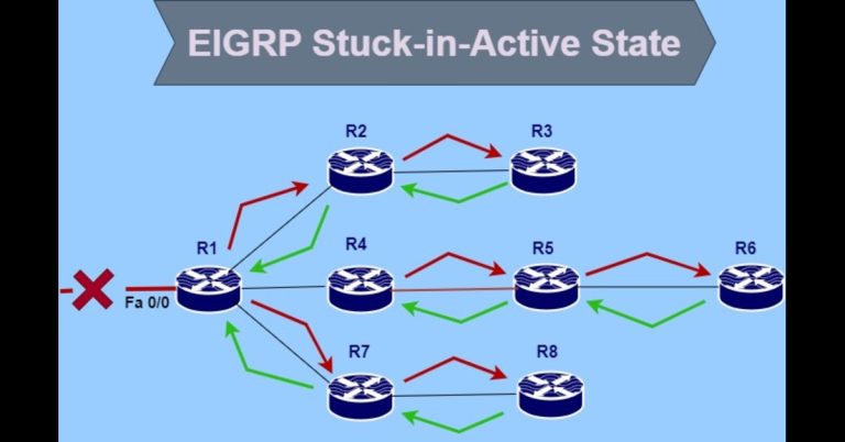
SNMP Notifications
SNMP uses traps and informs notifications. When any serious error occurs in the agent, then it sends it in the form of traps to inform the SNMP manager. If the SNMP manager doesn’t reply or respond to this trap in a certain period, then the agent again sends another notification, which is known as inform. The inform notification includes a request for receipt confirmation.
SNMP versions
There are three versions, which are v1, v2c and v3.
version 1
SNMP version 1 was developed in 1988. It uses plain-text community string for authentication. The community string is simply a password that provides access to the managed device’s stored data. Community string supports only by SNMPv1 and SNMPv2c. version 1 supports Get, Get-next, and set-operations.
version 2
SNMP v1 was enhanced and standardized as v2 in 1993. There are more The Getbulkpacket types than version 1. The Getbulk packet type feature was introduced in SNMP v2c. GetBulk means, to get multiple variables from the agent in one message. The SNMP v2c commands are get-request, get-bulk-request, get-next-request, inform-response, set-request and SNMPv2-trap.
version 3
SNMPv3 was introduced in 1998, which enhances security features, such as authentication and encryption. It uses a username and password for authentication along with an encrypted key instead of a community string. This version improves error handling and modification. SNMPv3 uses Engine ID, which uniquely identifies each device. It can identify duplicate EID, if any conflict occurs with a key. The Engine ID is used to generate a key for authenticated messages. SNMPv3 supports authentication and encryption. The authentication is used to ensure that only the intended recipient reads the trap. While encryption encrypts the SNMP messages to ensure its integrity.
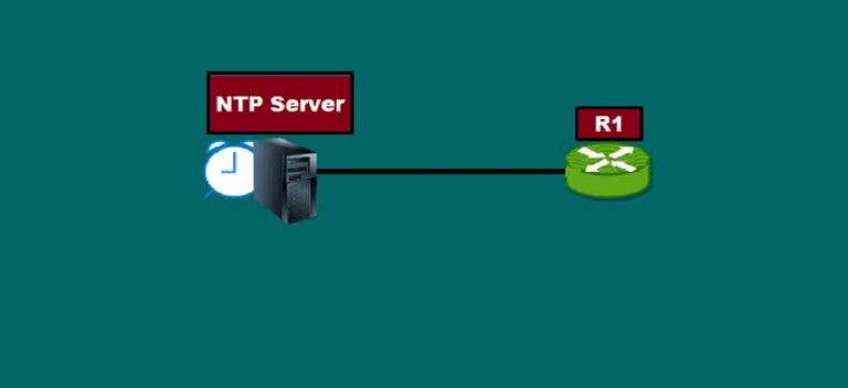
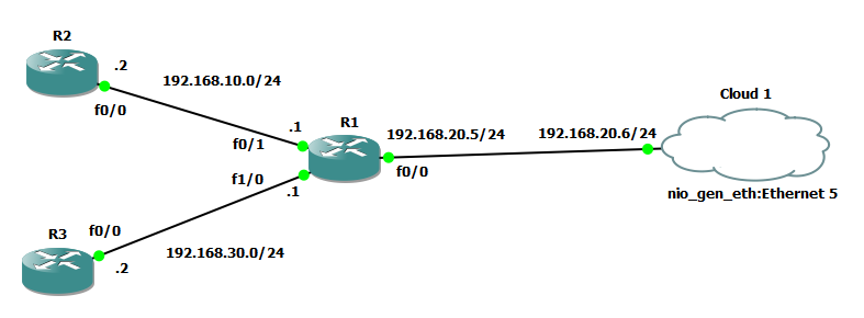
Lab Topology for SNMP configuration
Here we will use the following lab topology. Configure all the IP addresses as shown in the below screenshot.
SNMP V1 configuration and implementation in Packet Tracer
We will use the following lab topology for SNMP version 1 implementation:

Also, assign an IP address to the switch vlan 1.

Now run the two commands on Routers R1, R2, and Switch SW1.

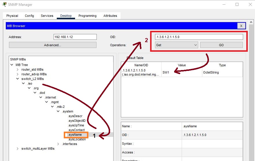
Click on a server in the Packet Tracer and there, click on “MIB browser”.

Configure the SNMP server for Router R1 as shown in the below screenshot: Enter the IP address of the Router R1, then click on advanced. Enter the read community string “read_only” while in Write Community, write “read_write” string. Select v1 from SNMP versions and then just click on ok. At the last select get, get-bulk, and set operations, whichever you want.

Expand the MIB. In the system, click on sysDescr and then go to Operations. select get operation and then hit go, then it will display the system information of Cisco ios.

If you want to extract the name of a router, then click on SysName. Go to Get and hit Go. It will display the Router name as R1 in the Result Table.

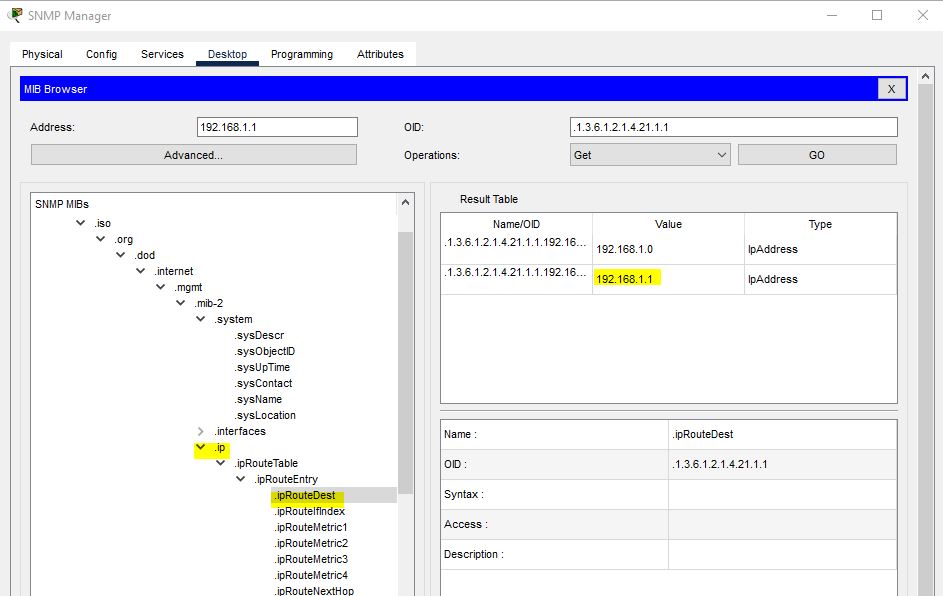
To display the Router IP, follow the following steps in the screenshot:
If you want to change the name of a router, then click on sysName. Go to Operations, select Set, and then click on GO. Select OctetString in Data Type and rename the Router as Router_R1. At the last click on OK.

The Router name has been changed to Router_R1.

If you want to get information on a Router R2, then enter the IP address of the Router R2.

Similarly, check the statistics of a switch. Write the IP address of a switch:

To check the name of a switch.
SNMP V2C Configuration
We will use this topology for SNMP v2c in GNS3.
The basic configuration of a router

How do I connect GNS3 Routers to My PC? First, I create two MS Loopback adapters in my own PC. Then, I assign IP address to these Loopback interfaces as below in the screenshot. But, if you don’t know, how to do it? How to connect a GNS3 router to a real PC/real network, then I have already published an article on this! Anyhow, the two Loopback adapters are shown in the screenshot:

In this lab, I have used the Power SNMP Network Manager tool for capturing SNMP traffic.

Go to PowerSNMP Network Manager and click on Devices, there click on Add Network Devices. A small window will appear as below in the screenshot and write the IP address of Router R1. Similarly, write the IP address of Router R2 in the same way.

Both Routers have been added to the network devices.

How to add agents? Just follow the following screenshot: Write click on SNMP Agents, and then click on Add Agent.

Write the IP address of an agent with version and port number and then click on OK.

So it will be shown as below:

You can add both the Routers to the Add Watch. Write click on any Router IP address in Agents and then click on Add. Similarly, also write the IP address of 2nd Router R2.

Both the Routers have been added to the Add Watch.

If you want to get some information about a router. Then click on the first 192.168.20.11:161 in the Agents. Go to MIB and expand it. Suppose I did Right Click on SysDesc. Then, it will display Router R1 mode with its IOS and some other basic information.

SNMP v3 Configuration
We will use the following simple lab topology for it:

Configure the SNMP v3 in the Router R1.

Now go to PowerSNMP Network Manager, and click on Devices. Click on “Add Agents”.

Explore the router setting for more necessary settings.