OSPF Routing Protocol: What you need to Know?
Introduction
OSPF routing protocol is a dynamic routing protocol that dynamically learns routes from other routers and advertises these routes to other OSPF-speaking routers. so that, these information will reach all the OSPF’s routers.
What is the OSPF routing protocol?
OSPF routing protocol is the most widely used IGP routing protocol. it uses IP protocol 89 for its communication. It works in a single A.S. Moreover; It supports VLSM and is classless. It has an administrative distance of 110. The OSPF routing protocol uses two multicast addresses; 224.0.0.5 and 224.0.0.6.
It uses the shortest path first algorithm for its routing. A famous mathematician Dijkstra designed this algorithm. That’s why this algorithm is called Dijkstra’s algorithm. It keeps track of other OSPF-speaking Router states, whether up or down.
Key Features of OSPF:
Key features of the OSPF routing protocol are;
1) Link-State Protocol: It uses a Dijkstra algorithm to maintain a complete map of the network topology
2): Fast convergence: Unlike distance-vector protocols, OSPF converges quickly than distance-vector routing protocol. It propagates changes in the network quickly, which ensures minimal downtime.
3)Hierarchical Design: It uses a hierarchical network structure with areas to optimize routing efficiency.
4) Open Standard: The main advantage of OSPF is its open source. That’s why every vendor’s device can support its functionality.
Types of OSPF
There are two types of OSPF, which are:
OSPF v2
OSPF v3,
While RFC 2328 defines OSPF v2 for IPv4 networks, OSPF v3 defined in 5340, is specifically designed for IPv6 networks. The major advantage of OSPV v3 is its extension for IPv6 addressing and other improvements in protocol operations and flexibility. It can also support Ipv4 through a technique of “dual-stack” deployment.
OSPF Router types
We divide OSPF routers into the following types based on their function.
- ABR: ABR stands for area border router. ABRs are those routers that are at the border of the area or which connect two areas. The ABR has two or more than two interfaces in different areas.
- Internal Router: The Router that is inside an area is called an internal Router, such a Router has all interfaces in one area.
- Backbone Router: Routers related to the backbone area or area zero. Such routers may have all interfaces in a backbone area or one interface in a backbone area.
- ASBR Router: ASBR stands for the autonomous system border Router. Those Routers which is located at the AS border or connect the OSPF autonomous system to the other Autonomous System.

Area Types

If our network grows and the number of routers increases up to 50 or 100 routers, then the Router will store 50 or 100 router information in its link state database. It is very hard for every Router to manage these Link state database information. There will be more consumption of RAM, CPU, and other resources of routers. If we don’t solve this problem in time, then there is a chance of latency in the network due to a heavy load on Router resources.
To solve this problem, we divide the OSPF large network into smaller logical parts, and these logical parts are called the OSPF area. We assign an identification number, known as area ID or area number, to such a logical area.
The area is hierarchical design. The backbone area must connect with all areas. The Link state database will store the area information to which it belongs and it will store summary information of other areas.
There are 5 types of areas in OSPF
OSPF uses a hierarchical design with areas to optimize traffic and simplify management. The most important area is the backbone area (Area 0), which all other areas must connect to.
- Backbone Area (Area 0): The area zero is also called the backbone area. It is the central hub for the OSPF routing protocol.
- Regular Areas: Non-backbone areas that connect to Area 0. All the other areas other than area 0 are called regular areas.
- Stub Areas: It is an area that prevents the advertisement of external routes, and thus reduces the routing table size.
- Totally Stubby Areas: NSSA Further restricts the advertisement for inter-area routes so that it reduces the routing size more.
- Not-So-Stubby Areas (NSSA): If you want to allow some external routes in NSSA, then you can use this area.
How Does OSPF Work?
The ospf working and operation are divided into three major categories.
- Neighbor relationship
- Database exchange
- Route calculation
1st of all OSPF Router establishes a neighbor relationship with other OSPF Router. The neighbor relationship decides whether the communication will be processed further or not. It lays the foundation of the OSPF network. Once the link is established, then all the OSPF-speaking Routers exchange their Link state database with each other. So that they share topology information. Once the OSPF Routers get LSDB from every OSPF speaking Routers, then it runs Dijkstra’s shortest path first (SPF) algorithm. It finds the best route calculation, and it stores the best route in its routing table. The Router uses a routing table to make the best decision about the shortest path.
OSPF Network Types
OSPF works differently depending on the type of the network. Understanding these types is challenging for optimizing OSPF operation:
1) Broadcast network: Broadcast network works is in an ethernet network, where all the routers communicate directly with each other. DR and BDR routers are elected in this type of network to reduce the number of adjacencies.
2) Non-Broadcast Multi-Access (NBMA): The famous WAN technology Frame Relay or ATM uses this type of network. In NBMA, the neighborship is configured manually and also DR/BDR election takes place.
3) Point-to-Point: The type of OSPF network where we connect two routers directly.
4) Point-to-Multi point: A type of network where multiple connections work as a series of point-to-point links. It is normally useful in hub-and-spoke topologies.
OSPF Router ID
To identify a Router in its entire network, there is a need for a unique identifier for each OSPF-speaking Router, which is called Router-id. The Router-id is a 32-bit number written in dotted decimal notation. The OSPF takes its Router-id from a Router interface IP. So the Router interface IP is the Router-id of an OSPF.
Rules for assigning OSPF Router-id
The ospf chooses its Router-id on the following factors.
- OSPF Router chooses the first Router-id if it is configured manually.
- If any Router-id is not configured manually, then it will select the Loopback address as its Router-id if is configured.
- The 3rd option is a physical IP address if there is neither a manual nor loop-back address is configured.
OSPF Neighbors Process
When one Router is connected to a second Router, then the first one shares information with the second Router. Then the 1st one, Router, is called a neighbor of the second Router. They are also called OSPF neighbors. To share information with other Routers in the OSPF network, first of all neighbor relationship is necessary. OSPF neighborship relationship has greater importance in the OSPF network. Some parameters are necessary before a neighbor relationship.
- Subnet and subnet mask used on the subnet
- Same hello and dead interval
- Same OSPF area-id
- OSPF Router must pass authentication
- Must match the ospf stub area flag
OSPF Neighbor States
There are eight neighbor states in the OSPF neighborship process:
- Down
- Attempt
- Init
- 2way
- Ex start
- Exchange
- Loading
- Full

- Down State: In Downstate, OSPF Router sends hello messages to its neighbor, but it doesn’t receive hello messages from its neighbor yet. Downstate occurs in two cases. First, if the Router is booted up for the first time, and second, if any link in the OSPF network goes down. Then the neighbor state converts into a down state.
- Attempt state: This occurs in an NBMA (non-broadband multi-access network) network where neighbors are manually configured. This state means that a router sends a Unicast message but the remote side of the Router hasn’t received it yet.
- Init State: This state means that a router receives a hello message from its neighbor but it doesn’t receive its Router-id in the hello message received from its neighbor
- 2way: The Router receives its Router-id in the hello message from a neighbor. They both receive Router-id in the hello message. The DR and BDR elections are taking place in this phase.
- Ex start: It stands for exchange start. The router starts the exchange process in this state. The master-slave relationship is established in this state. Before data exchange, initial sequence numbers are exchanged.
- Exchange: The Database description is exchanged in this phase. The Database description contains only LSA header information. Through this LSA header information, the receiver Router determines which LSAs are in its database and which are not.
- Loading: In this phase, the OSPF Router exchanges its Link state database and generates a Link state request. The LSR consists of missing LSAs. The master router replies to LSR with LSU (link state update).
- Full: OSPF-speaking routers synchronize the full database. This state is the ideal state for a router.
OSPF LSA Types
LSA is a type of data structure in OSPF. It relates to the link state by sending link state information to other routers. It will send information about what is the link type and to which router it is attached. LSA contains topology information.
Types of LSA
Router LSA 1: It defines the state and cost of the links to other routers within the same area.
Network LSA 2: LSA type 2 is generated by the DR router.
Area summary LSA 3: This LSA is generated by an ABR router, which summarizes routes to networks in other areas.
ASBR summary LSA 4: It points out the routes to the ASBR.
External LSA type 1 or LSA 5: LSA type 5 or external LSA advertises routes to the network outside of the OSPF Autonomous system. It is generated by the ASBR router.
External LSA type 2 or LSA 7: LSA type 7 is similar to type 5, but it is used in NSSA (Not-So-Stubby-Area) to allow external routes within an NSSA. ABR router converts it to type 5 LSA when necessary.
LSA type 8 or Link-LSA: This LSA is used in the OSPFv3 network, where it provides information about the link-local scope.
Intra-Area-Prefix LSA or LSA type 9: As its name suggests, it works within an area. However, this type of LSA works in OSPFv3 to advertise IPv6 prefixes within a specific area. Moreover, LSA type 9 is essential for propagating information about the IPv6 addresses that are reachable within the area. It can point to either LSA type 1 or LSA type 2, providing the necessary prefix information for routers to calculate their routing table accurately.
OSPF Packet Types
OSPF uses different types of packets for its communication.
- Hello: A hello packet is a common feature in every routing protocol. The purpose of a hello packet is to establish and maintain neighbor relationships.
- Database description or DBD: The DBD summarizes the contents of the link-state database.
- Link–State Request (LSR): When the Peer router requires any information about the specific link-state records, then it generates the Link-State Request (LSR) LSA.
- Link state update: This type of LSA is generated when the neighbor router requests any type of information. When a Router wants to send its LSA in the OSPF network to another OSPF-speaking router, then the router doesn’t send it directly to the other Router, but it sends its LSA through LSU. So LSU carries LSA from one router to another router. LSU may carry one or more than one LSA. The LSU may be periodic or triggered.
- Link-State Acknowledgement (LSAck): When the neighbor router receives any LSA, then it will reply with LSAck, that the requested LSA has been reached successfully.
OSPF Hello and Dead interval
The hello and dead interval are the two important factors on which OSPF-speaking routers will make their relationship. It has a great importance after forming their relationship. OSPF hello and dead intervals maintain OSPF speaking routers in up and down states.
- OSPF hello interval is a time in which OSPF speaking Router sends a message in a specified time period to ensure its existence in the network
- While OSPF Dead interval is a time in which OSPF Routers mark its neighbor Dead if the hello message is not received for a specified time.
to check OSPF hello and dead interval
R1#show ip ospf neighbor

How to change OSPF hello and dead interval

And check the result of the above configuration.

How to Calculate OSPF Cost Metric
The OSPF metric is based on cost. The cost metric is used to find the best path from source to destination. Every interface is configured with the cost, which is based on bandwidth. The greater the bandwidth, the lower the cost, and the router will install the routes at having lower cost. The cost metric can be configured dynamically or manually.
The cost value may be from 1 to 65535. The router will prefer the lower link cost because the cost is inversely proportional to the interface bandwidth But a link with a higher cost means it will not be preferred by the Router.
If you don’t want to configure it manually, then the router will calculate it based on the bandwidth configured on a link.

The default value of the reference bandwidth is 100 Mbps. For example, for the fast ethernet interface. Reference bandwidth will be divided by fast ethernet (100 Mbps), which will yield the cost = 1.

| S.No | Interface | Cost |
| 1 | 1 Gbps | 1 |
| 2 | 100 Mbps | 1 |
| 3 | 10 Mbps | 10 |
| 4 | DSL (1.54 Mbps) | 64 |
| 5 | DSL (768 Kbps) | 133 |
The OSPF calculates the cost for each route on the outgoing interface.
Check the cost of the link

Now change the cost of the link of the fast ethernet 0/0 of R2;

Now check the interface cost, whether the cost has been changed or not.

You can change the reference bandwidth through the following command.

how to configure OSPF
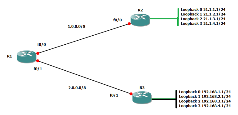
The following lab topology consists of three routers with their LAN. Area 0 is running on R1, R2, and R3, while area 1 is on R1’s fast ethernet 0/1 and area 2 on R3’s fast ethernet 0/0. Moreover, Configure the IP addresses on all three routers and then run OSPF on them.

configure IP addresses and run OSPF on R1.

Configure of R2;

Similarly, configuration of R3:

Check the routing tables of all the routers:

At the last check the connectivity among all the routers through the ping command:

Now run additional commands on R1 to explore OSPF. If you want to know which routing protocol is running on my router, then run the command, “show ip protocol”.

The OSPF is running on the router with process ID 1. You have found that OSPF is running on the router. Now, run another command “show ip ospf 1”, which will explore further features of OSPF.

The “Show IP OSPF neighbor” command will list all the neighbors.

Now, at last, run the “show IP ospf database” command to wind this blog post.