Spanning Tree Protocol Basics and Configuration Made Simple!
Introduction
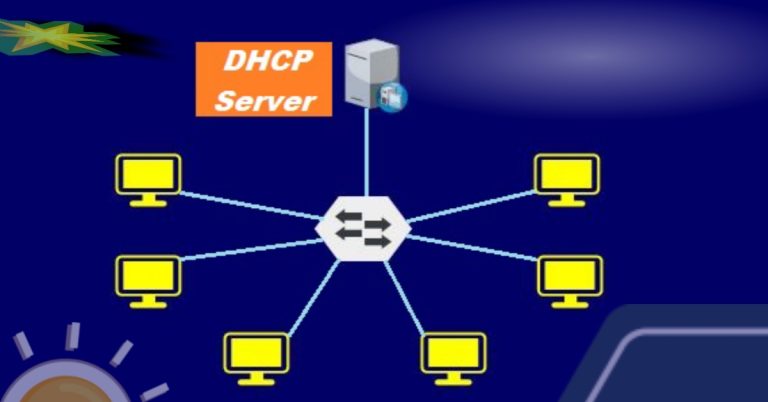
Spanning tree protocol or STP is a layer 2 protocol that converts circular or redundant paths in a computer network into a treelike structure where nodes will have no loops. A tree in a computer network is a structure in which nodes are connected to the root switch. STP disables redundant links into block ports. The purpose of the STP on switches is to make a loop-free network. By default, switches run IEEE 802.1d, which does not need to configure it. spanning tree protocol configuration We will use the following lab topology for STP.
spanning tree protocol configuration
We will use the following lab topology for STP.

- Configure the trunk link between all three switches
- Set the vtp domain as marwat
- Configure the VTP mode server on all the switches
- Create a vlan 10 on Switch1
- Assign access ports to the PCs connected to all three switches. Also, assign vlan to all three PCs connected to the switch1, switch2 and switch3
Check the root switch by running the command “show spanning-tree” on switch1;

Switch1 has been elected as the root bridge. The root bridge depends on the spanning tree priority values as well as on the mac address, which is collectively known as bridge ID. First, it will check the priority value, and if the priority values are the same, then the switch with the lowest MAC address will be elected as the root switch.
The bridge ID is 8 bytes of which 2 bytes are for priority and 6 bytes are for MAC address. The switch with the lowest BID will become a root bridge.
Configuring Primary and Secondary Bridge
If you want to change the root switch or root bridge, then you can change it through the following commands. But, we will set switch2 as the root switch or root bridge for VLAN10 and the secondary root for vlan1. In the same way, set Switch3 as the root switch for vlan1 and the secondary switch for vlan10.

Some time ago, switch1 was acting as the root switch, but check it now;

Switch2 will act as the root switch for vlan10 and secondary for vlan1 as below in the screenshot;

At the last, check switch3;

Spanning Tree Protocol Link cost
The spanning-tree protocol uses a link or path cost assigned to the link. It is a numerical value that is assigned to a network link or path to determine the most efficient path for forwarding data within a switched network. It helps STP to prevent loops in the Layer 2 topology. The link cost with the associative speed is given in the table form;
| Link Speed | Default Cost |
| 10 Mbps | 100 |
| 100 Mbps | 19 |
| 1 Gbps | 4 |
| 10 Gbps | 2 |
STP prefers the lowest-cost link to the root bridge. If two or more paths have the same cost value, then the link with the lowest bridge ID will be elected. But, if they have also the same BID, then the port with the lowest physical interface number will be elected (lowest port ID). Consider the following lab topology for link cost;

Run the “show spanning-tree” command on switch1, and then check the port cost;

Also, run the same command on switch2;

The port Fa 0/2 at switch1 is blocking, we will lower its cost from 19 to 16 through the following command;

Now run the command “show spanning-tree” command on Switch1 again to check differences;

Before configuring the cost on switch1 Fa 0/2, it was blocking, but now it has been converted into a root port due to its lower cost;
Port Priority
Port Priority also influences the port which port should be placed in the forwarding state and which port will be blocked if multiple links exist between switches. Port ID is a combination of Port Priority + Port Number as
Port ID = Port Priority + Port Number
Port ID = 128.1, 128 is a priority value and 1 is an interface value (Fa0/1). However, the default port priority is 128. The priority value ranges from 0 to 240, and it is in increments of 16. Again, use the below diagram for learning port priority.

Run the “show spanning-tree” command to check port priority values on switch1;

Switch2 is the root bridge and Fa0/2 of switch1 is in the blocking state, while Fa0/1 is in the forwarding state. The default port priority or port number is 128.2 for Fa0/2, where 128 is a priority value and is the interface value (0/2). But we will change this number to make it Root port towards the root bridge in the following screenshot.

We have decreased the port priority from 128 to 32, so check it on Switch1;

Switch1 Fa0/2 has been converted into a root port, while Fa0/1 is now blocking. Now, let’s check the priority value of Fa0/2 at Switch2, which is 32.

The switch2 is the root bridge, so it didn’t affect its interface.